Build plans / Circuit Demonstration Boards
Circuit Demonstration Boards
This is a family of simple wooden boards, each built around one idea: bulbs in series and parallel, batteries in series, batteries in parallel, a two-switch 'three-way' light, a one-or-the-other switch puzzle, a diode that only lets current through one way, and a continuity tester for checking what conducts. They share the same construction methods (bolt terminals, clip leads, trimmed battery holders), so once you have built one, the rest go quickly.
Written from Bruce's original workshop handout. Bruce's final review of this plan is in progress.
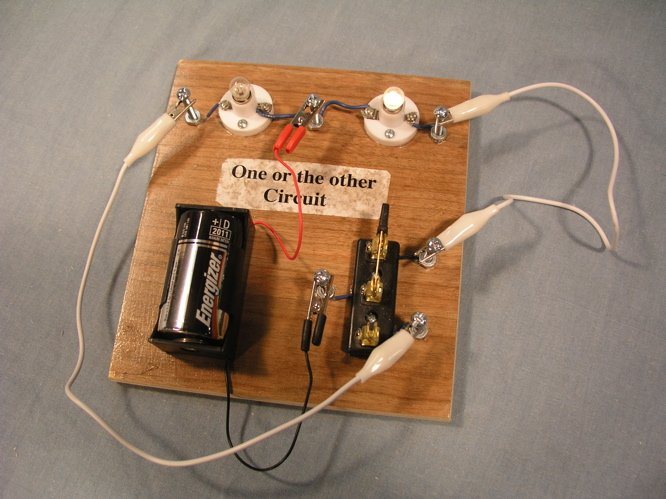
What it shows
Seven small wooden boards turn abstract circuit diagrams into bulbs that students can light, dim and puzzle over with their own hands.
Key ideas: series circuits, parallel circuits, voltage, switches, diodes, complete circuits, conductivity, ions in solution
Build it
Make the boards
Cut a board for each circuit from 1/4 in plywood, sand the edges and varnish it. Lay out the parts before drilling anything so the wiring paths are short and easy for students to trace.
Add bolt terminals
Drill holes for small bolts wherever a student will need to clip on a lead. Wrap a bare wire end around the bolt under the board or under a nut on top, and tighten the nut down against the wood to clamp it. Bolts make far more reliable connection points than bare wire.
Trim the battery holders
Store-bought holders have tall side walls that make it hard for small hands to remove cells. Cut part of each side wall away with a small saw, or with a utility knife blade warmed so it slices the plastic. Leave enough of the holder to grip the cell.
Make clip leads and strain relief
Crimp a ring terminal onto one end of a lead so it can be bolted down, and solder or crimp an alligator clip onto the other. Where battery leads leave the board, loop them through a small screw eye so a tug does not pull on the solder joints.
Board 1: bulbs in series and parallel
Mount a battery holder and three bulb bases. Run two bus wires of bare 12 gauge house wire from bolt to bolt along the board and connect the battery to the nearest bolts on each bus. Bolt a clip lead to each terminal of every bulb base so students can clip each bulb across the buses (parallel), chain bulbs end to end (series), or mix the two.
Board 2: batteries in series
Mount a bulb base at one end and three battery holders end to end along the board. Wire them in a chain: the far end of the first holder runs on a long wire to the bulb, its other end joins the next holder, and so on, with the last holder returning to the bulb's other terminal. At each junction add a bolt with a short jumper clip lead so students can bridge across an empty holder and run the board with one, two or three cells.
Board 3: batteries in parallel
Mount a bulb base and three battery holders. Join all the red (positive) leads together and all the black (negative) leads together, scraping a little insulation off each and soldering the joints. Run the positive bundle to one side of the bulb base and the negative bundle to the other.
Board 4: three-way switch
Mount a one- or two-cell battery holder, a bulb base and two double-throw knife switches. Attach the wires to the switches from the underside before screwing them down. One battery lead goes to the center (common) terminal of the first switch; its two outer terminals connect by two wires to the two outer terminals of the second switch; the second switch's common goes to the bulb, and the bulb returns to the battery.
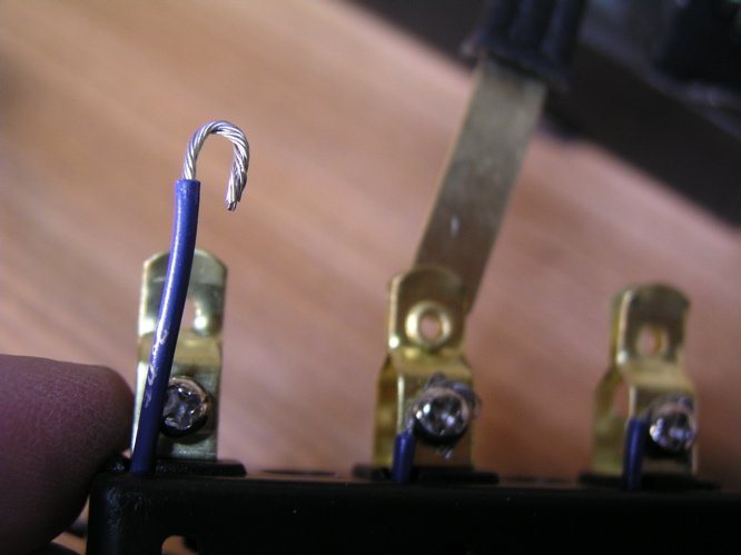
Board 5: one-or-the-other puzzle
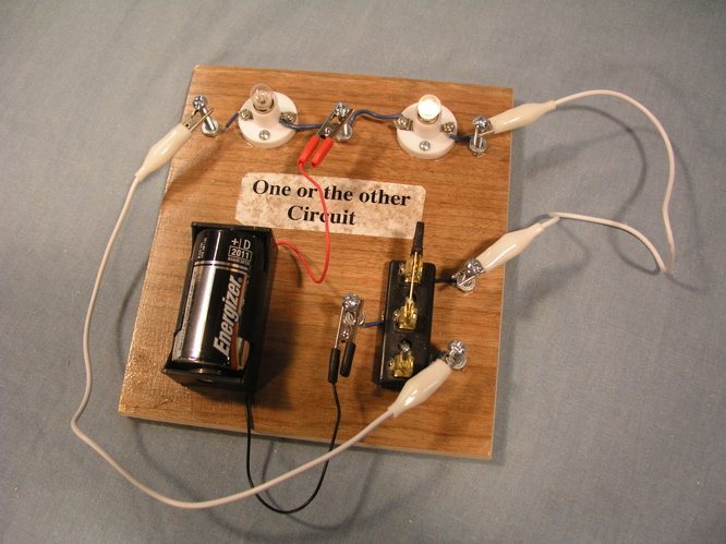
Run three wires from a double-throw switch under its base to three bolt terminals, then screw the switch down. Mount two bulb bases, join one terminal of each bulb to a shared bolt with a single wire, and give each bulb's other terminal its own bolt. Put alligator clips on a battery holder's leads and supply two loose clip leads. Leave it unwired: the students' job is to make the switch light one bulb or the other.
Board 6: diode tester
Mount a battery holder, a bulb base and three bolts labeled A, B and C. Wire the bulb base between bolts B and C, then wrap the diode's leads around bolts A and B and tighten the nuts on them. Extend the battery leads (solder or crimp), run them through a screw eye for strain relief, and finish them with alligator clips.
Board 7: continuity tester
On a small board, about 3 x 4 in, screw down a bulb base and a 9 V battery clip, and screw in two 1 in bolts as probe terminals. Wire one battery lead to the first bolt, the other battery lead to the bulb base, and the bulb base to the second bolt. Strip both ends of two 1 ft pieces of 14 gauge wire, wrap (and if needed solder) one end of each around a bolt, and tighten the nuts down; the free ends are the probes.
Label and test each board
Print labels on a computer printer, lay them into wet varnish and add a few more coats so they will not peel. Test every board with fresh cells before handing it to students.
How it works
In a series circuit there is only one path, so the same current passes through every part. Add a second bulb in series and the battery's voltage is shared between them, so the current drops and both glow dimmer. In parallel, each bulb gets its own path straight across the battery, so each gets the full voltage and glows as brightly as a single bulb would.
Batteries in series add their voltages: 1.5 V, then 3 V, then 4.5 V, and the bulb gets brighter with each cell. Batteries in parallel keep the voltage at 1.5 V, so the bulb's brightness does not change; what changes is how long the set can keep it lit, because the cells share the load.
A three-way light uses two double-throw switches connected by two 'traveler' wires. The light is on whenever both switches point to the same traveler, so flipping either switch changes the state. This is the same idea that lets you control a stairway light from the top or the bottom.
A diode is a one-way valve for current. Connected one way (forward biased) it conducts with only a small voltage drop, about 0.7 V for a silicon diode; reversed, it blocks current and the bulb stays dark. Electrons in the wires actually flow from the negative terminal toward the positive one, which is opposite to the 'conventional current' arrow printed on the diode.
The continuity tester is a circuit with a gap in it. Whatever you bridge the probes with becomes part of the circuit: a good conductor lights the bulb fully, a poor one dimly, an insulator not at all. Dry salt does not conduct because its ions are locked in a crystal, and pure water has very few ions, but dissolve the salt and its sodium and chloride ions are free to move, carrying current through the water. Tiny bubbles on the probes are hydrogen and oxygen from the electrolysis of water.
Using it
- Series and parallel: compare one, two and three bulbs in series, then in parallel. Then wire two bulbs in series alongside a single bulb in parallel and ask why the single bulb is much brighter.
- Batteries: show the series board with one, two and three cells and ask what changed. Then do the same on the parallel board and ask why nothing visible changed.
- Three-way switch: ask students to draw the layout and trace the path of the current for each combination of switch positions, then explain how either switch can turn the light on or off.
- One-or-the-other: give students the board, the battery clips and two test leads and challenge them to make the switch light the left bulb in one position and the right bulb in the other. Then have them draw their solution and trace both paths.
- Diode: clip the battery to B and C and the bulb lights either way round. Move one clip to A so the diode is in the circuit, and the bulb lights only when the battery faces one way. Ask students to figure out which end of the diode must face the positive terminal.
- Continuity tester: have students sort classroom objects into conductors and insulators, check whether bulbs and fuses are good, and test liquids. Try dry salt, tap water and salt water. Then test household ammonia and vinegar separately (both are poor conductors because they form few ions), mix a little of each and test again: the mixture conducts well because the reaction makes many more ions. Look for bubbles on the probes.
Variations
- Add a fourth bulb to the series-parallel board for longer chains.
- Use a buzzer or small motor in place of a bulb on any of the boards.
- For the diode board, try a light-emitting diode (with a suitable resistor) to show a diode that lights up itself.
- Continuity tester with a buzzer: wire a small 9 V buzzer in place of the bulb. Bruce found it more sensitive, since the pitch changes as resistance changes, but warns that a room full of buzzers gets annoying quickly.
Troubleshooting
More build plans
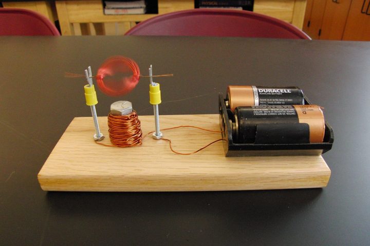
No-Magnet Motor (Double-Coil Motor)
Students who have built the classic coil-and-magnet motor are always surprised that it still spins when the magnet is swapped for a coil of wire around a bolt.
Tangent Galvanometer
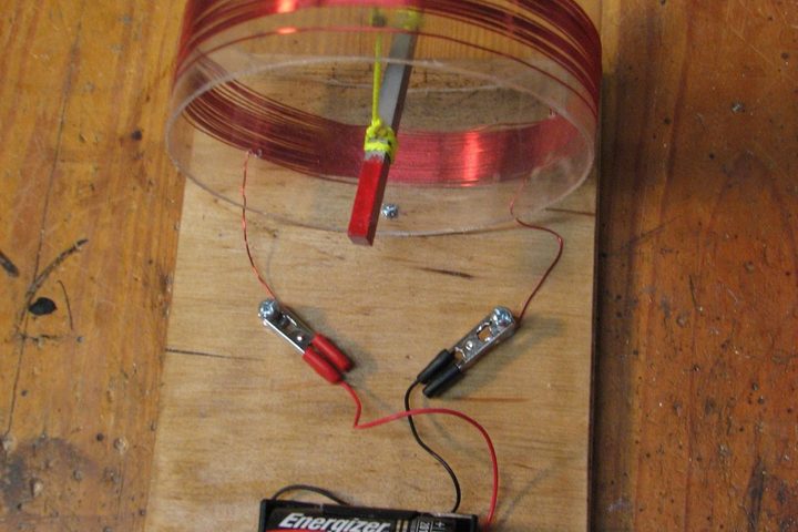
Clip on one wire and a hanging bar magnet swings to face across a ring of copper wire; reverse the battery and it spins all the way around.
Glove Light Bulb
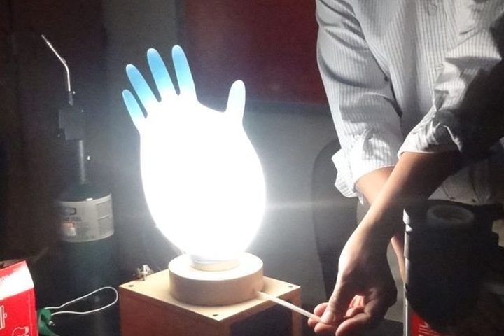
Who says a light bulb has to be made of glass? This one glows inside a rubber glove.
© Bruce Yeany · Homemade Science with Bruce Yeany · youtube.com/@YeanyScience
Free for personal and classroom use. Please don't resell or republish. Build and use at your own risk; follow the safety notes and supervise children.